The Fender HOT series of amps were made in the early '90s as an entry level practice amp. They were single transistor solid state amps rated at 25 watts output power through an 8 inch speaker. They feature four front panel switchable "voicings", two on the clean channel and two on the drive channel. As far as controls other than the voicing switches, there are three knobs: "Contour", "Volume", and "Reverb". The contour knob adjusts the relative bass-treble, and the reverb knob adjusts the amount of reverb that is mixed in from the three spring Accutronics reverb tank mounted on the base of the cabinet.
Here's a picture of mine as it looked when I got it:

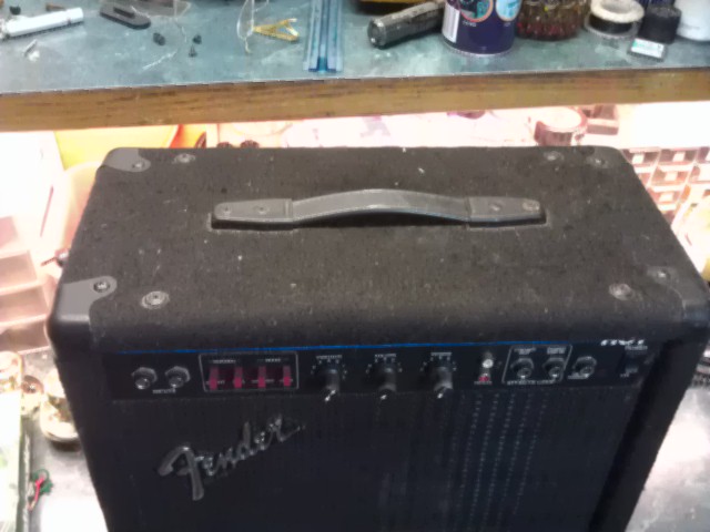
This is what it looks like now:

These amps overall are fairly derided by the guitar player community as not being flexible with their sound and/or just sounding like crap all together. I played through this little baby a bit before I started working on it, and for what I need, it sounds fine. It'll never sound like a '65 Twin Reverb, but then, it's NOT a '65 Twin Reverb. "It is, what it is."
But anyway, enough about that, let's get on with it...
When I received this amp, it had most definitely seen better days. Covered in the original black cloth, the previous owner had also had a golden retriever, so the thing was literally covered in dog hair. I spend about three hours with masking tape, and a stiff scrub brush, and still never got all the hair off of it. That, coupled with the fact that it had been sitting on a carpeted floor and the aforementioned dog (I believe) though it was a fire hydrant, let me to the decision to strip it down and recover it.
This is how it looked when I first put it on my work bench:


Ahh yes, genuine made in the USA electronics:

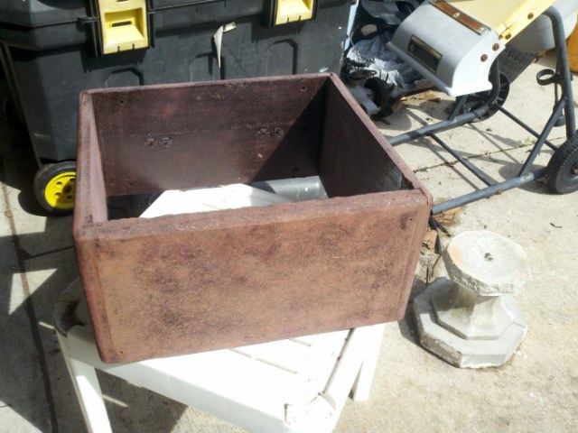
First order of business: Strip all of that cloth off of there! Since this was my first attempt at doing this, I asked advice from my family seamstress (thanks Mom!), and pulled off the covering off in a single piece so as to use it as a pattern to cut the new cover. I recommend this approach to anyone planning this kind of project. Here it is, all stripped of the cloth:


The box itself was in good shape for pressed wood construction. There was a little swelling on the lower front lip from moisture intrusion (dog again), but I was able to sand that down since the damage was old, and the wood long since dried. I took the box to my family wood-worker, and we decided the best approach was to soak the entire thing in sealer to prevent any re-occurrence of liquid intrusion (thanks Ziggy).


After that, I gave it a light sanding on the surface so that the spray adhesive would adhere good:


I gave the center of the inside faces a shot of black spray paint where they are not covered:


Also sanded and sprayed the speaker baffle:


The inside of the cabinet top which is over the exposed portion of the actual amplifier circuitry, was lined with metal-aluminum tape like that used in the air conditioning industry, but the way it was applied, when I was disassembling everything it started to get pulled up in pieces. Rather than trying to salvage it for reuse, I decided I would just replace it. However, since nobody makes this stuff for consumers in 10 inch wide rolls, I used what I had on hand, 2 inch wide aluminized-mylar tape:


Now, it was time st start applying the new cover. I had some really nice gray vinyl that was a curb-find, and as it turns out, there was just enough for this project. I used 3M Super '77' spray adhesive, giving both the wood, and the vinyl a good coating before laying down the covering, and then got to it:


The original covering was two pieces; a single piece going all the way around the box, and a small piece covering the lower valance in the back. The vinyl I had gotten wasn't quite long enough to replicate that, so I ended up with three pieces; A single piece covering the top and both sides, a piece for the bottom, and a piece for the valance. I used my staple gun to reinforce the adhesive at the edges to help keep them from curling and pulling up. I laid the staples such that they would not be seen when it was completed. The only place I didn't use staples was on the very bottom face, and the back valance. I also applied another layer of tape to the underside of the top to give it a little more isolation (I hope).

Now that the covering is finished, time to turn my attention to the amp circuits:


Not much to the guts of this baby. Since it worked fine when I got it, I really didn't want to do much to the circuit. I gave it some good blasts of compressed air to clean all the dust and dog hairs out of the insides, I pulled all the knobs and jack nuts off so I could pull the circuit board back away from the face, gave it a good cleaning and a brief wipe with an Armour All wipe for good measure. (Sorry, didn't take pictures of this)
When I was working on getting the circuit board loose, one of the things I had to do was to pull the power leads off the switch. This is normally not a problem since they are just spade connectors. However...when Fender built this, they used connectors on the mains leads that have little tabs on them which go into the little hole in the middle of the spade connector on the back of the switch. I was unable to see this when I was trying to get the switch out because the mains leads are on the physical bottom of the switch (white & black wires in this pic:

So, due to my not seeing this, I was using needle nose pliers to pull the leads off and ended up pulling the entire spade connector out of the back of the switch, necessitating a replacement power switch.
Since I now had everything opened up, I decided to add a little custom touch and replaced the red square LED power indicator with a more tasteful looking blue LED in a chrome bezel. I metered the power going to the LED to be 18 volts DC, and kept trying different value resistors on my blue LED to get the brightness that I wanted...bright enough to see, but not too bright. I finally ended up with using a 1 Meg Ohm resistor which dims the bright blue down to a really nice level.
Before:

After:

And a better shot of the brightness:


Now that I had my new power indicator installed, and switch replaced, the only thing left to do was to put it all back together. I repainted all of the hardware, and since all four of the bottom corner protectors were quite rusted (the dog again), I ordered new cabinet corners, painted them and put it all together. On a side note; you will notice that the speaker I have in it now is different than the one that was in it to begin with. That's because when I was disassembling the unit, I accidentally put my fat thumb through the paper cone of the original speaker. I had this speaker in an extension speaker cabinet, and it was the same size, and rating, so in it went. I Googled the part number on it and found out that, even though it is not branded, it is a Kustom brand built speaker. So that's cool. Just another "kustom" touch.


Also, repainted the black around the script of the Fender logo, as it was chipped in several places:

Last thing I did was to screw rubber feet onto the bottom of the cabinet so that this little baby will sit OFF of the floor.

So it's finished, and now I think it looks better than when it left the factory in California in 1990. Tell me what you think.

Here's a before & after (thanks Sis):

Things to do now that it's done...ROCK IT!!! :)
Seriously though, I think I am going to replace the control knobs with red ones to match the switches. I have also tossed around the idea of building an entirely new cabinet for it. I have some REALLY nice 7 layer plywood from some old shelves that would make an awesome looking cabinet done in a natural finish, or a light to medium stain. Other than that, I might add an extension speaker jack on the back. If I want to get just crazy, I could replace the output circuit to put it up to 50 watts...we'll see.
No comments:
Post a Comment